In the second of new series of technical blogs, StreetDrone is going to explain the hierarchy of a “robotic” self-driving system, and how that translates into the movement of a self-driving car.
Our “Hello World!” series is written by software engineer Efimia Panagiotaki, a tech-trotter with engineering experience ranging from the National Technical University of Athens to ETH Zurich to Williams Formula 1. Efimia is leading the development of StreetDrone’s autonomous driving software by leveraging Autoware, a ROS-based, open source self-driving stack.
Sense — Plan — Act
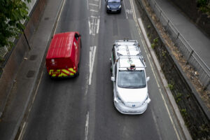
The automotive industry is racing towards building fully self-driving cars, so that you, me and everyone can make one of our wildest dreams come true: drink and not drive.
Jokes aside, driverless cars are here not only to take us home after a wild night out, but to reduce accidents, casualties and fatalities in general by removing the human error out of the equation. As it is not an easy thing to solve, until today, and even though there have been millions of miles travelled autonomously, we are still far from removing the safety driver from behind the steering wheel.
Companies and Start-ups are working towards developing the most reliable and robust software stacks, ensuring hardware and software redundancy and optimizing system performance in urban and rural environments, highways etc.
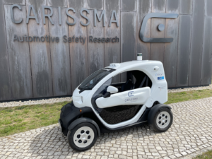
Each system integration is well defined by a set of conditions in which each vehicle can operate autonomously. StreetDrone is a safety-led autonomous urban trials company, with well defined Operational Design Domains (ODD), under which a StreetDrone vehicle can operate autonomously [Source: Defining the conditions for Autonomy].
StreetDrone’s software stack is optimized to ensure safety and reliability on challenging ‘zone 1’ restrictive metropolitan environments our vehicles are designed to run. To facilitate the debugging and a better understanding of the vehicle’s functionality, our software architecture follows the traditional robotics approach in autonomous systems. It consists of independent, interchangeable modules (or packages), separating the functionality of the pipeline. To break down the complexity of the software pipeline and design, develop and debug the software stack, we have used ROS (Robots Operating System) as middleware or a bridge for the communication between the algorithms.
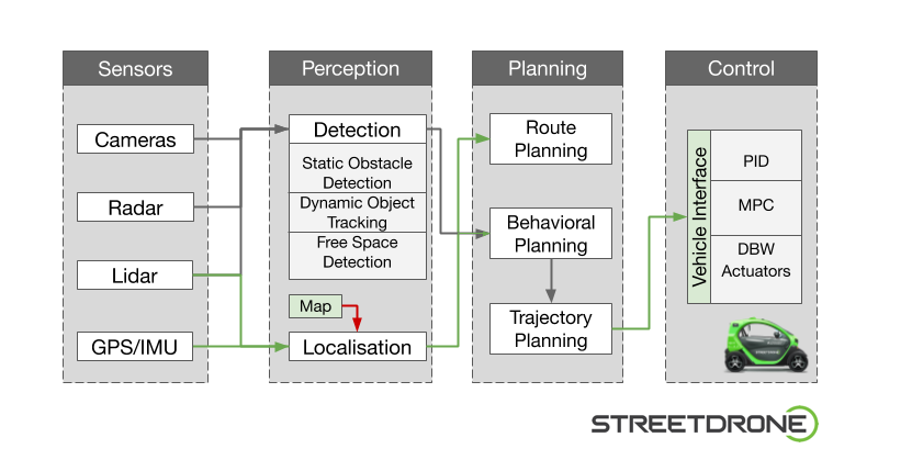
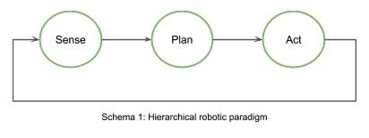
Following the robotic paradigm, the software stack can be described by the relationship between the three primitives of robotics: Sense — Plan — Act. These primitives best explain how a robot operates by describing how the sensors data are being processed and distributed for a decision to be made. In the case of an autonomous mobile robot (aka self-driving vehicle), we are following the hierarchical paradigm where a robot senses the world, plans the next actions and then acts.
Our pipeline can be divided into separate subsystems, all communicating with each other:
- Perception Subsystem
- Planning Subsystem
- Controls Subsystem
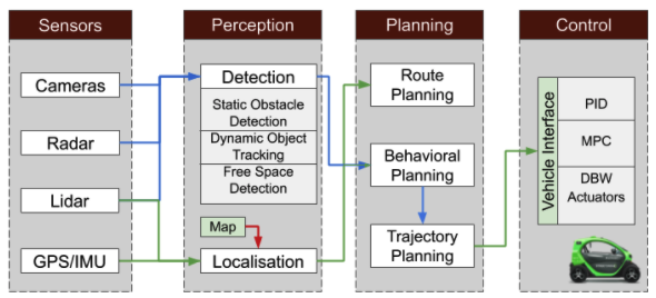
1. Perception Subsystem:
This is the vehicle’s centre of understanding its environment. It receives the sensors’ output to perform 3D scene reconstruction and to make decisions about the vehicles’ surroundings.
This subsystem can be divided into the detection module and the localisation module. Using the information from the cameras, the lidar and the radar, the vehicle performs static obstacle detection, dynamic object tracking and free space detection to determine the vehicle’s ability to move freely and safely inside a desired path. The detection module is responsible for understanding the surrounding environment of the vehicle.
The pipeline relies heavily on pre-recorded lidar maps of the environment, extracted from driving the path manually, retrieving the desired point cloud data which are then processed into a map. The localisation module determines the vehicle’s precise location using the lidar data and the extracted map and comparing the two point clouds.
2. Planning Subsystem:
The processed information from the perception subsystem is then being used as input to the planning subsystem in order for this to calculate the vehicle’s path. It can be divided into the route planning, the behaviour planning and the trajectory generation modules.On the route planning step, we are extracting the waypoints of the path we would like the vehicle to follow. This refers to the high-level path between two points on a map. Using as input the information from the localisation module and the Inertial Navigation System (INS), at the behaviour planning step, the software decides what manoeuvre our vehicle should take in order to stay in that path, calculating the final velocity. Finally, the resulting plot of the precise path our vehicle will follow is being extracted on the trajectory generation module.
3. Control Subsystem:
The final path determines the target velocity (linear and angular) of the vehicle at each waypoint. The vehicle interface is responsible for controlling the vehicle and for translating the velocity requests into low-level state vehicle commands; throttle, brake, steer. To make sure that the vehicle is behaving as desired, PID controllers are implemented using a control loop feedback mechanism to control process variables in the most accurate and stable manner. Another way of process control used to satisfy a set of constraints is the Model Predictive Control (MPC), which has been vastly used in autonomous vehicles control subsystems.
The controls subsystem is responsible for controlling the vehicle and for ensuring the communication between the drive by wire system and the high-level autonomous driving algorithms.

Please stay safe and stay at home so we can all build more robot cars together 🙂